As systems grow and scale across multiple services, teams face challenges like service communication, data consistency, fault tolerance, and deployment strategies.
The good news is that many of these challenges have well-established solutions in the form of design patterns.
These patterns are battle-tested approaches that architects and engineers use to solve common problems in distributed architectures.
Understanding these patterns helps you make better architectural decisions, avoid common pitfalls, and build systems that are resilient, scalable, and maintainable.
In this post, we will explore 12 distributed system Design Patterns that every architect should know:
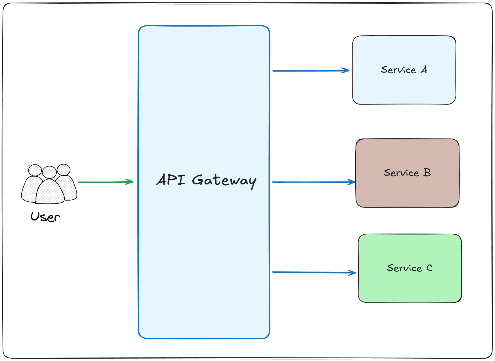
An API Gateway is a single entry point that sits between clients and your backend services.
It acts as a reverse proxy that routes requests to the appropriate microservices.
It often handles cross-cutting concerns like authentication, rate limiting, and request transformation.
How it works:
The client sends all requests to a single API Gateway endpoint instead of calling individual services directly
The API Gateway receives the incoming request and performs authentication and authorization checks
It applies rate limiting and throttling rules to protect backend services from overload
The gateway routes the request to the appropriate microservice based on the URL path or request headers
It can aggregate responses from multiple services into a single response for the client
Benefits:
Simplifies client implementation by providing a single endpoint instead of managing multiple service endpoints
Provides a layer of abstraction that allows backend services to change without affecting clients
Improves security by hiding internal service structure and endpoints from external clients
Drawbacks:
Introduces a single point of failure that can bring down the entire system if not properly designed
Can become a performance bottleneck when handling high traffic volumes
Adds latency to every request due to the additional network roundtrips
Use cases:
Microservices architectures where multiple services need to be exposed through a unified interface
Systems that require consistent authentication and authorization across multiple services
Legacy system modernization where you need to facade old services behind a modern API
Point To Point Async Integration is a communication pattern where one service sends messages to another service through a message queue.
Unlike synchronous calls, the sender does not wait for an immediate response and continues processing, while the receiver consumes messages from its queue at its own pace.
This creates an asynchronous but still direct relationship between two services.
How it works:
Service A sends a message to a dedicated queue that only Service B consumes from
The message queue acts as a buffer between the sender and receiver, storing messages until consumed
Service A continues processing immediately after sending the message without waiting for a response
Service B processes messages from its queue independently at its own pace
The message broker guarantees message delivery and can persist messages for reliability
If Service B is temporarily unavailable, messages accumulate in the queue until it recovers
Dead letter queues can handle messages that fail processing after multiple retry attempts
Benefits:
Decouples services in time, allowing sender and receiver to operate at different speeds
Improves resilience as temporary failures in the receiver don't affect the sender
Provides natural load leveling as the queue buffers messages during traffic spikes
Enables asynchronous processing for long-running operations without blocking the sender
Simplifies scaling the receiver independently by adding more consumer instances
Drawbacks:
Introduces message broker as a dependency that must be managed and can become a single point of failure
Creates eventual consistency as the sender doesn't know when or if the message was processed successfully
Makes debugging more difficult as message flow is asynchronous and indirect
Use cases:
Background job processing where immediate responses are not required
Order processing systems where orders are queued for fulfillment services
Email or notification services that process requests asynchronously
Systems with uneven load patterns where queues provide buffering
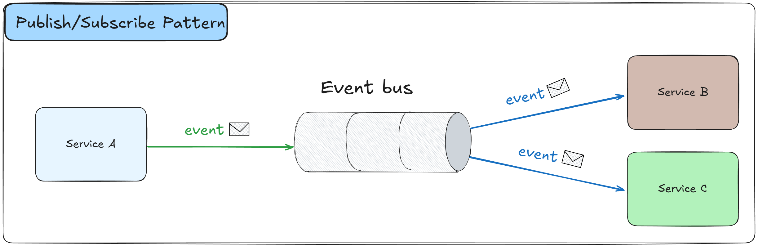
The Publish/Subscribe Pattern is an asynchronous messaging pattern where publishers send messages to a central message broker or event bus without knowing who will consume them.
Subscribers register their interest in specific types of messages and receive them automatically when they are published, creating a loosely coupled event-driven architecture.
Here is the main difference between Publish/Subscribe and the Point To Point Async Integration pattern:
Publish/Subscribe assumes that there can be multiple subscribers for a single event type
Point To Point Async Integration assumes there is only one subscriber for each event type
How it works:
Publishers send messages or events to topics or channels on a message broker without knowing about subscribers
The message broker receives and stores messages, managing the distribution to multiple subscribers
Subscribers register their interest in specific topics or event types they want to receive
When a message is published, the broker automatically delivers copies to all active subscribers
Multiple subscribers can receive the same message independently, each processing it according to their needs
The pattern supports one-to-many communication where a single event triggers multiple actions
Subscribers can be added or removed without requiring changes to the publisher
Message filtering can be applied so subscribers only receive messages matching specific criteria
Benefits:
Decouples publishers from subscribers, allowing independent development and deployment of services
Enables scalability by allowing multiple subscribers to process messages in parallel
Supports event-driven architectures where services react to changes rather than polling for updates
Makes it easy to add new functionality by introducing new subscribers without modifying existing code
Improves system resilience as failures in one subscriber don't affect publishers or other subscribers
Drawbacks:
Introduces message broker as a dependency that must be managed and can become a single point of failure
Makes debugging and tracing more difficult as message flow is asynchronous and indirect
Can lead to eventual consistency challenges as different subscribers process messages at different times
Requires careful design to avoid message ordering issues and duplicate message handling
Use cases:
Event-driven architectures where multiple services need to react to the same business events
Systems that require real-time notifications to multiple consumers like chat applications or dashboards
Microservices that need to maintain data consistency through integration events
Integration scenarios where new services need to consume existing events without modifying publishers
Workflows that involve multiple steps handled by different services, triggered by a single event
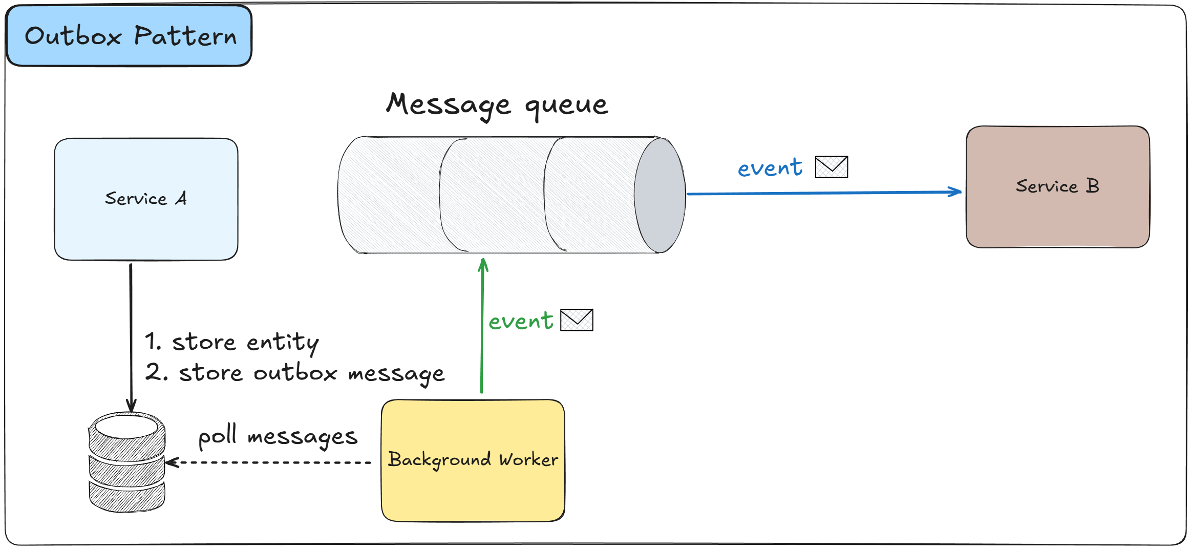
The Outbox Pattern ensures reliable event publishing by storing events in a database table (the outbox) within the same transaction as the business data changes.
A separate process reads from the outbox and publishes events to the message broker, guaranteeing that events are published if and only if the business transaction succeeds.
How it works:
When a service modifies business data, it also inserts event records into an outbox table within the same database transaction
The database transaction ensures atomicity between business data changes and event creation
A separate background process or worker continuously polls the outbox table for unpublished events
The background process reads events from the outbox and publishes them to the message broker
Once an event is successfully published, it is marked as processed or deleted from the outbox table
If publishing fails, the event remains in the outbox and will be retried automatically
The pattern eliminates the dual-write problem where data is saved but events fail to publish
Events are guaranteed to be published at least once, though subscribers must handle potential duplicates
Benefits:
Guarantees that events are published if the business transaction succeeds, preventing data inconsistencies
Eliminates the dual-write problem where database commits succeed but message publishing fails
Provides a reliable audit trail of all events in the system stored in the database
Allows for event replay and recovery scenarios by keeping a history of published events
Drawbacks:
Introduces eventual consistency as events are not published immediately but after polling
Requires additional infrastructure for the outbox processor and monitoring
Can create performance overhead due to additional database writes and polling operations
Needs careful handling of duplicate events on the consumer side due to at-least-once delivery (you can use InBox pattern with Idempotence checks to avoid this)
Use cases:
Microservices that need to guarantee event publication after data changes
Systems implementing event sourcing where every state change must be captured as an event
Any scenario where data consistency between services is critical and message loss is unacceptable
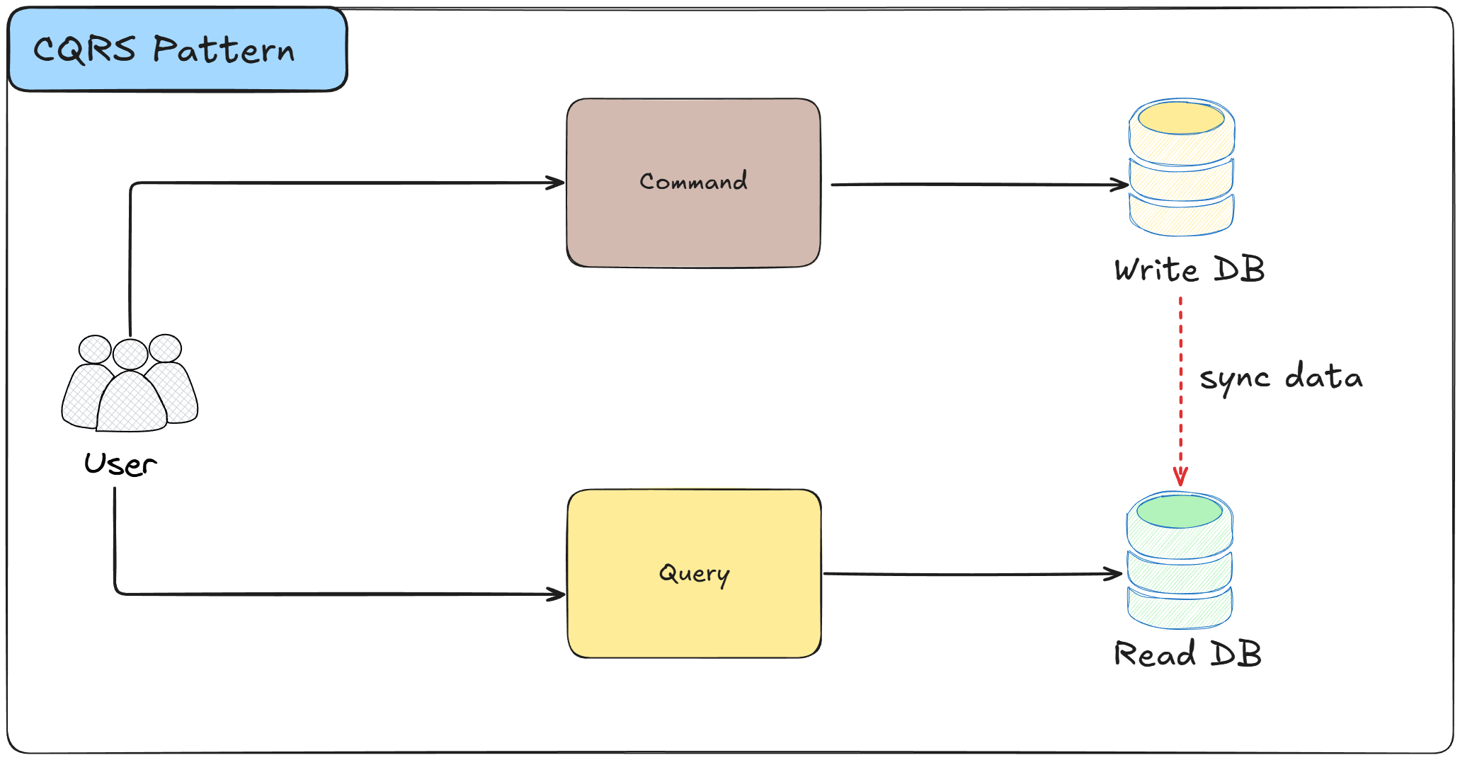
CQRS is a pattern that separates read operations (queries) from write operations (commands) by using different models for each.
The write model handles business logic and data modifications, while the read model is optimized for querying and reporting.
How it works:
Commands represent actions that change the system state and are processed through the write model
The write model enforces business rules, validates data, and persists changes to the database
Queries retrieve data through the read model without modifying any state
The read model is often a separate database or data structure optimized for query performance
Changes made through the write model are propagated to the read model asynchronously, often through events
Benefits:
Allows independent optimization of read and write models for their specific performance requirements
Enables scaling read and write operations separately based on actual usage patterns
Simplifies complex domain models by separating command validation logic from query logic
Drawbacks:
Introduces eventual consistency between write and read models
Increases system complexity with multiple models and synchronization mechanisms
Requires additional infrastructure to keep read and write models synchronized
Use cases:
Applications with significantly different read and write loads requiring independent scaling
Complex domains where business logic for writes differs greatly from reporting requirements
Systems with high read-to-write ratios where query performance is critical
The Saga Pattern manages distributed transactions across multiple services by breaking them into a sequence of local transactions.
Each local transaction updates data within a single service and publishes an event or message to trigger the next step.
If any step fails, compensating transactions are executed to undo the changes made by previous steps, maintaining data consistency across services.
How it works:
A saga is initiated when a business process requires changes across multiple services
The saga coordinator breaks the distributed transaction into a sequence of local transactions, one per service
Each service executes its local transaction and publishes an event indicating success or failure
The coordinator listens to these events and triggers the next step in the sequence
If all steps complete successfully, the saga finishes and the distributed transaction is considered complete
If any step fails, the coordinator executes compensating transactions in reverse order to undo previous changes
There are two implementation approaches: choreography (services coordinate through events) and orchestration (central coordinator manages the flow)
Benefits:
Enables distributed transactions across microservices without requiring distributed locks or two-phase commits
Maintains data consistency through compensating transactions instead of rollbacks
Allows long-running business processes to span multiple services with better fault tolerance
Scales well as each service manages its own local transactions independently
Drawbacks:
Introduces complexity in designing and implementing compensating transactions for every step
Creates eventual consistency which can lead to temporary inconsistent states visible to users
Makes debugging and monitoring more difficult as transactions span multiple services over time
Can lead to complex error handling scenarios when compensating transactions themselves fail
Use cases:
Multi-step workflows in enterprise systems where each step is handled by a different service
Any business process that requires coordinated changes across multiple microservices without distributed locks
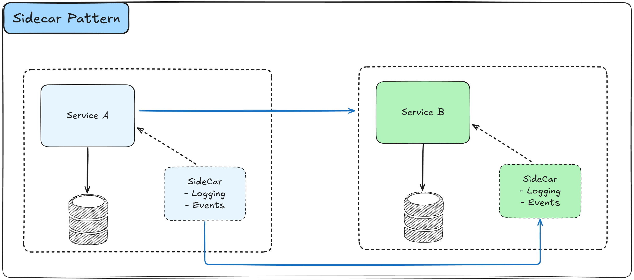
The Sidecar Pattern deploys a helper component alongside your main application container that provides supporting features like logging, monitoring, configuration, or networking capabilities.
The sidecar runs in the same execution environment as the main application and shares the same lifecycle, allowing it to extend functionality without modifying the application code.
How it works:
A sidecar container is deployed alongside the main application container in the same container or host
Both containers share the same network namespace, allowing communication through localhost
The sidecar can intercept incoming and outgoing traffic and handle cross-cutting concerns like logging, metrics collection, or service mesh functionality
Communication between the application and sidecar happens through local network calls
Updates to sidecar functionality can be deployed independently without changing the application
Multiple sidecars can be attached to a single application for different purposes
Benefits:
Separates infrastructure concerns from application code, keeping the codebase focused on business logic
Enables polyglot architectures as sidecars work with any application language or framework
Simplifies application development by providing reusable infrastructure components
Allows independent updates to infrastructure features without redeploying applications
Reduces code duplication across services by centralizing common functionality in sidecars
Drawbacks:
Increases resource consumption as each application instance runs additional sidecar containers
Adds complexity to deployment configuration and orchestration
Can introduce latency due to additional network hops between application and sidecar
Use cases:
Service mesh implementations providing traffic management, security, and observability
Centralized logging where sidecars collect and forward application logs to logging systems
Configuration management where sidecars fetch and update configuration dynamically
Event-driven integration where the sidecar handles messaging through pluggable queue implementations (e.g., Kafka, RabbitMQ, Azure Service Bus) allowing seamless switching between them without modifying the main application (e.g., using Dapr).
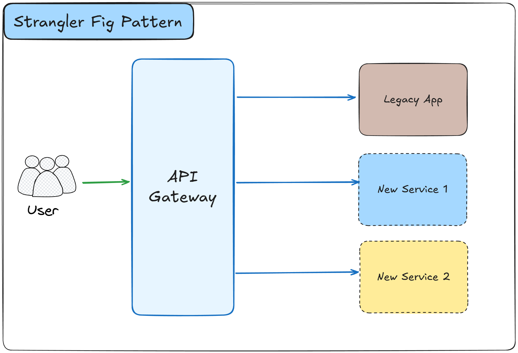
The Strangler Fig Pattern is a gradual migration strategy that replaces a legacy system by incrementally building a new system around it.
This pattern routes new functionality to the new system while the legacy system continues handling existing features until it is completely replaced and can be retired.
How it works:
A facade or routing layer is placed in front of the legacy system to intercept all incoming requests
New features are implemented in the new system instead of the legacy codebase
The routing layer directs requests to either the legacy system or the new system based on the feature
Existing functionality is gradually migrated from the legacy system to the new system in small increments
Both systems run in parallel during the migration period, with the legacy system handling less over time
Benefits:
Reduces risk by allowing gradual migration instead of risky big-bang rewrites
Enables continuous delivery of value as new features can be released during migration
Minimizes disruption to users as the system remains operational throughout the migration
Drawbacks:
Increases operational complexity by requiring maintenance of two systems simultaneously
Requires additional infrastructure for routing, synchronization, and data consistency
Makes testing more complex as both systems need to be validated during the transition
Use cases:
Modernizing legacy monolithic applications by migrating to microservices architecture
Replacing outdated technology stacks with modern frameworks and languages
Moving on-premises systems to cloud-based solutions incrementally
Refactoring systems with poor code quality or technical debt
Any large-scale system replacement where downtime and risk must be minimized
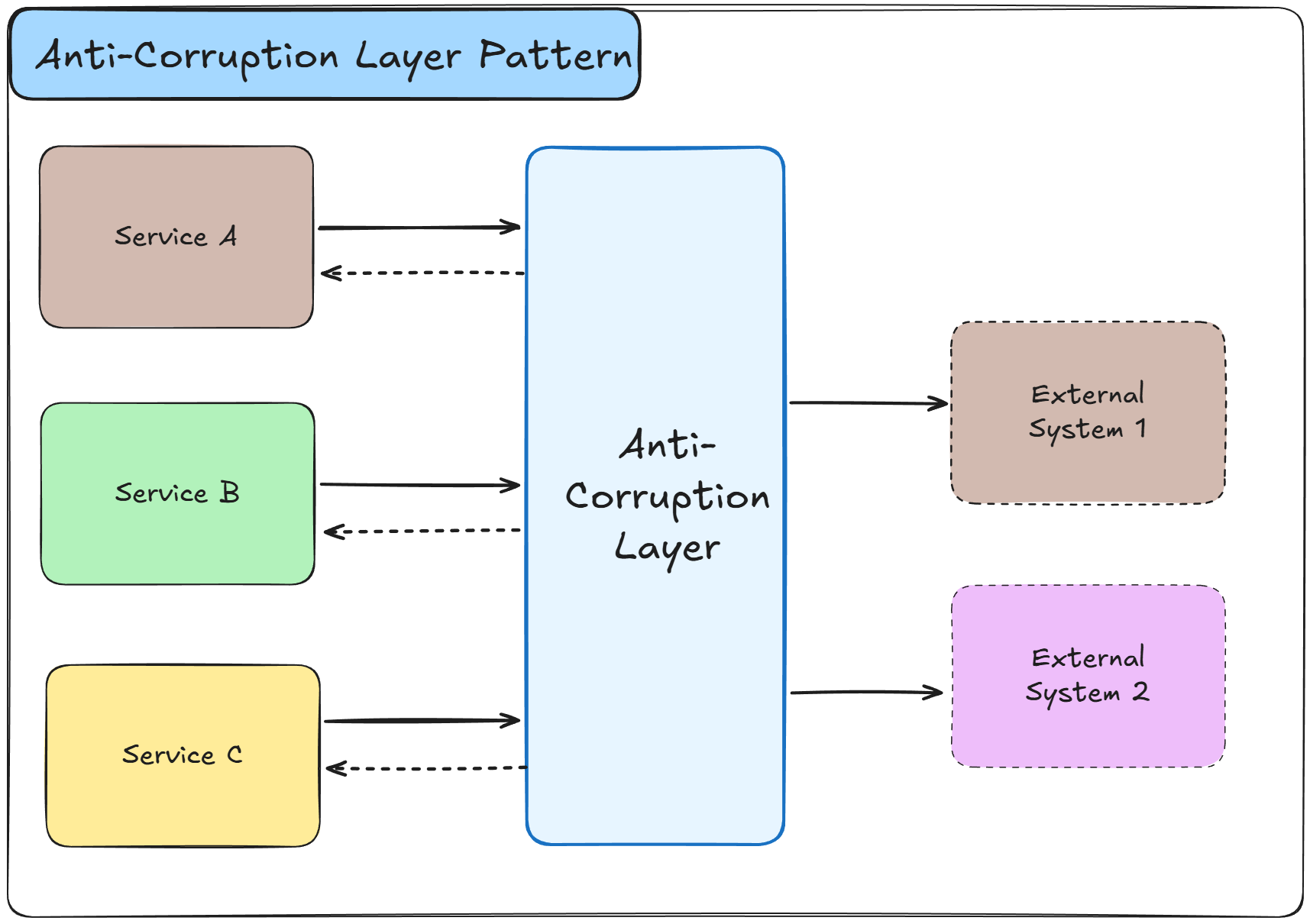
The Anti-Corruption Layer Pattern creates a protective boundary between your domain model and external systems or legacy code.
This layer translates between different models, preventing external concepts and structures from polluting your domain design and allowing your system to evolve independently.
How it works:
An anti-corruption layer sits between your domain model and external systems or legacy services
The layer acts as a translator, converting external data structures and concepts into your domain language
When your system needs data from external sources, the layer fetches it and transforms it
Your domain code only interacts with the anti-corruption layer, never directly with external systems
The layer shields your domain from changes in external systems by absorbing the integration complexity
It can aggregate multiple external calls into single domain operations
Benefits:
Protects your domain model from external changes, keeping it clean and focused on business logic
Allows your system to evolve independently without being constrained by external system designs
Simplifies testing by providing a clear boundary for mocking external dependencies
Makes it easier to replace external systems as integration logic is centralized in one layer
Drawbacks:
Adds development effort as translation logic must be written and maintained
Introduces an additional layer that can impact performance due to data transformation overhead
Requires careful design to avoid the layer itself becoming a bottleneck or overly complicated
Use cases:
Integrating with third-party APIs that have different domain models or terminologies
Protecting microservices from legacy system complexities during gradual modernization
Working with external systems that have poor data models or inconsistent interfaces
Building systems that need to remain stable despite frequent changes in external dependencies
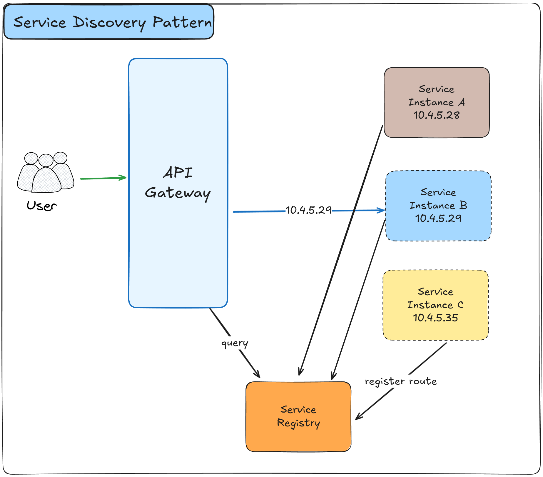
The Service Discovery Pattern enables services to find and communicate with each other dynamically without hardcoding network locations.
As services scale up or down, move between hosts, or get replaced, a service registry maintains an up-to-date map of available service instances and their network addresses, allowing clients to locate services automatically.
How it works:
A central service registry maintains a catalog of all available service instances and their network locations
When a service starts, it registers itself with the service registry, providing its address and metadata
The service sends periodic heartbeats to the registry to indicate it is still healthy and available
If a service fails to send heartbeats, the registry automatically removes it from the available instances list
When a client needs to call a service, it queries the registry to get the current addresses of available instances
The client receives a list of healthy service instances and selects one based on load balancing strategies
There are two main approaches: client-side discovery where clients query the registry, and server-side discovery where a load balancer queries it
The registry can be distributed across multiple nodes for high availability and fault tolerance
Popular implementations include Consul, Eureka, etcd, and Kubernetes DNS-based service discovery
Benefits:
Enables dynamic scaling as services can be added or removed without configuration changes
Improves resilience by automatically routing traffic away from failed instances
Simplifies deployment as services don't need to know the exact locations of dependencies
Supports multiple environments and regions where service addresses differ
Drawbacks:
Introduces the service registry as a critical dependency that must be highly available
Adds network latency due to registry lookups before making service calls
Increases complexity in the overall system architecture and deployment
Use cases:
Microservices architectures with dynamic scaling where service instances change frequently
Cloud-native applications deployed across multiple availability zones or regions
Container orchestration platforms like Kubernetes managing hundreds of service instances
Systems requiring automatic failover when service instances become unhealthy
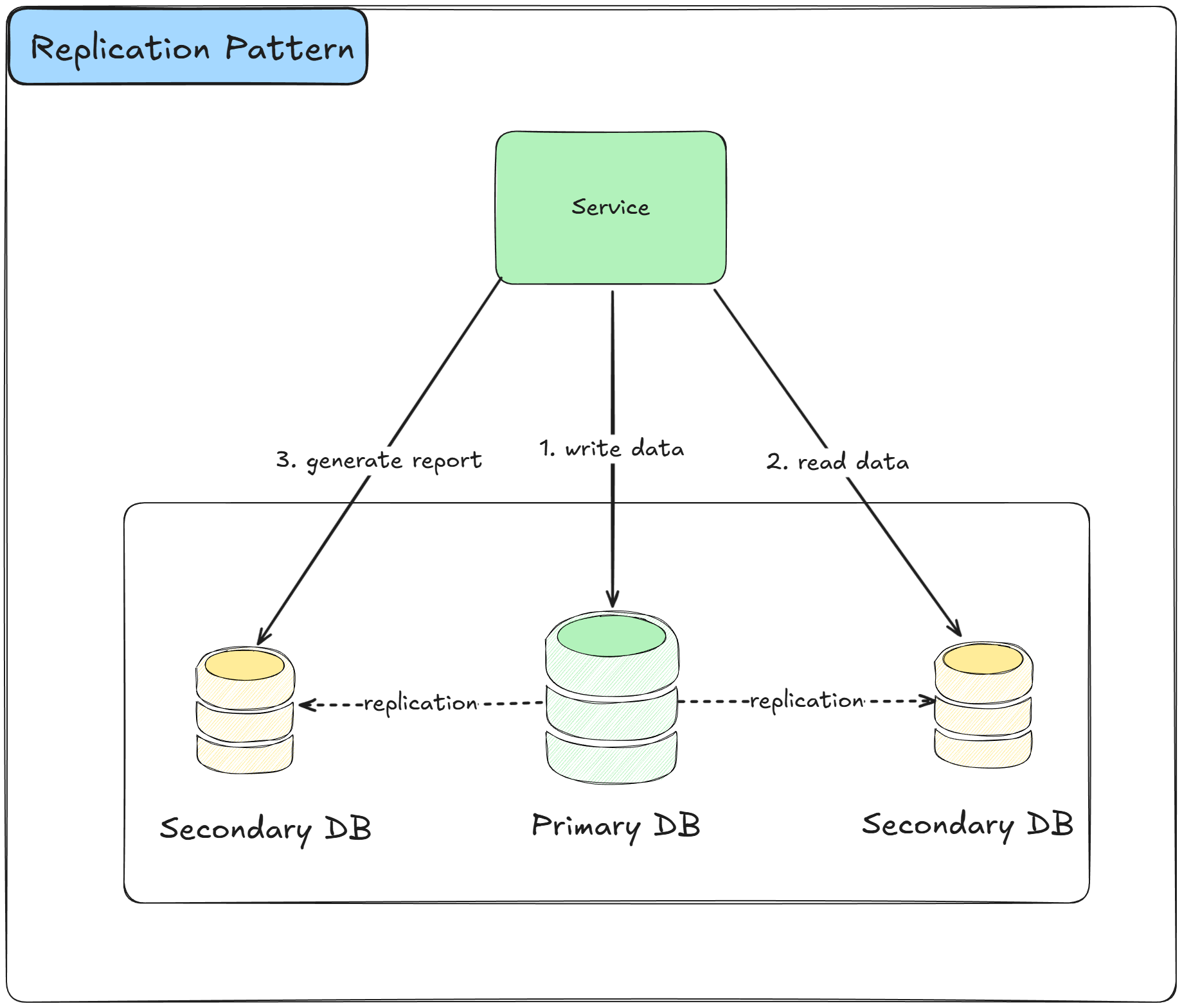
The Replication Pattern creates multiple copies of data across different nodes or databases to improve availability, fault tolerance, and read performance.
Data changes are propagated from the primary node to replica nodes, ensuring that multiple copies stay synchronized and the system can continue operating even if some nodes fail.
How it works:
A primary node receives all write operations and serves as the authoritative source of data
Changes made to the primary are replicated to one or more replica nodes automatically
Replication can be synchronous, where writes wait for replica confirmation, or asynchronous for better performance
Replica nodes can serve read requests, distributing query load across multiple nodes
When the primary fails, one of the replicas can be promoted to become the new primary
Different replication topologies exist: primary-replica, multi-primary, and peer-to-peer replication
The pattern often combines with sharding, where each shard has its own replication setup
Benefits:
Improves read performance by distributing queries across multiple replica nodes
Increases availability as the system continues operating if the primary node fails
Provides disaster recovery capabilities with geographically distributed replicas
Enables zero-downtime maintenance by taking replicas offline without affecting service
Protects against data loss through multiple copies of critical data
Drawbacks:
Introduces eventual consistency where replicas may temporarily have stale data
Increases storage costs as data is duplicated across multiple nodes
Adds complexity in handling failover and ensuring replicas are properly synchronized
Can create conflicts in multi-primary setups requiring complex resolution logic
Use cases:
High-availability systems requiring continuous operation despite hardware failures
Global applications serving users from multiple geographic regions with low latency
Read-heavy workloads where distributing queries improves overall system performance
Disaster recovery scenarios requiring data copies in different data centers
Systems requiring point-in-time recovery or backup replicas for data protection
Distributed system design patterns provide proven solutions to common architectural challenges, but each comes with important trade-offs.
For example:
The API Gateway simplifies client communication but introduces a potential bottleneck.
Event-driven patterns like Publish/Subscribe and Outbox enable loose coupling but create eventual consistency.
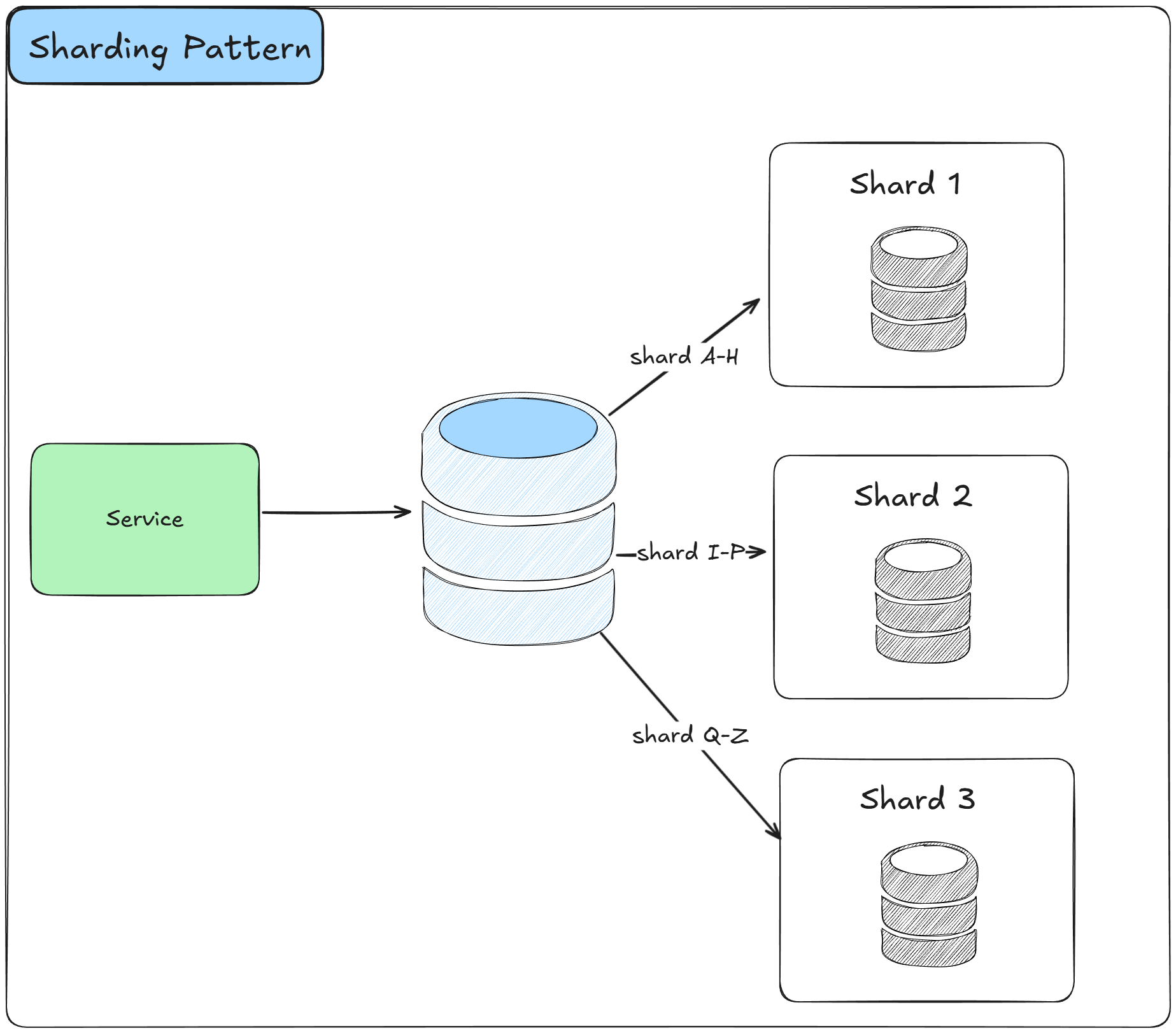
CQRS and Sharding improve performance at the cost of increased complexity.
Understanding these trade-offs and knowing when to apply each pattern is the essential skill of every architect.
The right architectural decision depends on your specific context, constraints, and whether you can accept the trade-offs that come with each pattern.
Hope you find this newsletter useful. See you next time.
Whenever you're ready, here's how I can help you:
The .NET Senior Playbook is built to:
Fast-track you from junior or mid-level to senior
Keep you growing as a senior
Help you beat any .NET interview
Covers everything: C#, ASP.NET Core, EF Core, system design — answer each question first, reveal the solution, and a test after every chapter proves it stuck. Finish, and you earn a verifiable certificate for your LinkedIn.
Not sure where you stand? Take the free .NET Interview Run:
Find out your real level — Junior to Senior+
A realistic mock .NET interview — across 13 areas of C#, .NET, ASP.NET Core and System Design
No credit card required. When you finish, you get a personalized report: your level, your strongest and weakest areas, and where to focus next — the perfect way to benchmark yourself before diving into the Playbook.